ARTIFICIAL NEURAL NETWORK for the PREDICTION of FATIGUE LIFE of FLEXIBLE FOLDABLE ORIGAMI STRUCTURE
“We present a comprehensive fatigue analysis of a foldable origami helical antenna with Finite Element Method (FEM) and Artificial Neural Network (ANN). We study the effect of design parameters such as length ratio (b/a), height of story, total height, thickness, length and thickness ratios of creases, and radius of the circumscribed circle of polygonal on the fatigue life. We employ ANN method to reduce the computational cost of the conventional methods for predicting the fatigue life of the origami antenna. Although ANN is trained with a limited set of data, our results reveal that the proposed approach predicts the fatigue failure of the antenna with high accuracy. This trained ANN determines the life cycle of the origami structure with less than 1% error on the training set and less than 2% error on the test set. The ANN results indicate that the life cycle of the structure is improved by increasing the radius of the circumscribed circle and decreasing the thickness of the structure. We discover that some values of the length ratio (b/a) magnify the effect of total height on the life cycle. In addition, we show how the creases parameters of the structure play an important role in the fatigue life of the antenna” Fig. 1. 
Figure 1: Artificial Neural Network (ANN) of the Prediction of Fatigue Life of Origami Structure
- Related article: Submitted to the Journal of Thin-Walled Structure. Nov. 2021
PREDICTION OF FATIGUE LIFE OF A FLEXIBLE FOLDABLE ORIGAMI STRUCTURE WITH KRESLING PATTERN
“We present a thorough mechanical analysis of a foldable origami helical antenna using the Kresling pattern. A precise simulation is required to explicitly capture the complex motion of an origami structure during the folding process. We perform this study by employing the Finite Element Method (FEM) available in ANSYS software. First, we analyze the folding behavior of the structure with three stories. The results indicate that after the second story is folded completely, the first and third stories begin to fold. Next, we predict the fatigue life of the structure using the mean stress with fully reversed loading. We investigate the effects of several design parameters such as length ratio (b/a), height of story, total height, thickness, length and thickness ratios of creases, and radius of the circumscribed circle of polygonal on the fatigue life. We find out that the origami structure with the length ratio (b/a) of 1.9 has the highest life cycles. The results indicate that the effects of the height of the story on the life cycle depend on the length ratio (b/a). We observe that the life cycle of the origami structure improves by decreasing the thickness or increasing the radius of the circumscribed circle of hexagonal. In addition, we discover that the creases design plays an important role in the fatigue life and folding behavior of the origami structure” Fig. 2.
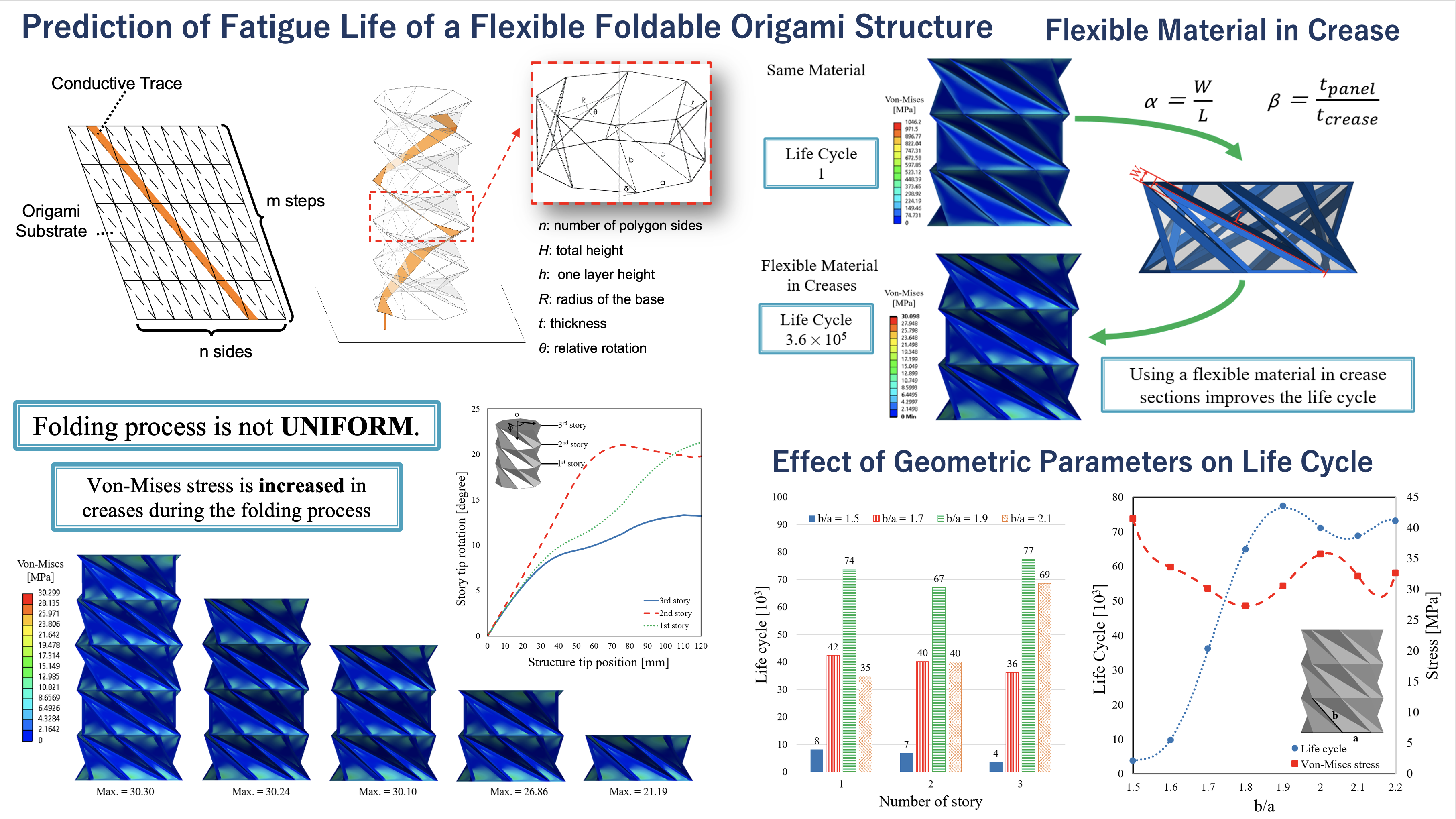
Figure 2: Prediction of Fatigue Life of a Flexible Foldable Origami Structure
- Related article: Mojtaba Moshtaghzadeh, Ehsan Izadpanahi, Pezhman Mardanpour: Prediction of fatigue life of a flexible foldable origami antenna with Kresling pattern, Engineering Structures, Volume 251, Part A, 2022. http://10.1016/j.engstruct.2021.113399
STABILITY ANALYSIS OF FLEXIBLE FOLDABLE RECONFIGURABLE ORIGAMI STRUCTURE
“A reconfigurable structure of antenna improves electromagnetic (EM) performance and its capability compared with other designs. The design satisfies both EM and mechanical needs simultaneously. Our studies the stability analysis of a foldable helical antenna with the Kresling origami pattern, which is subjected to tip follower force. The structure of the antenna is simulated using the geometrically-exact, fully intrinsic nonlinear composite beam theory of Hodges. The cross-sectional properties of the antenna’s structure are obtained using the Variational Asymptotic Beam Sectional (VABS) analysis. While the results of the stability analysis are in agreement with commercial finite element tools, the numerical platform developed in this paper offers significant computational advantages. In a case study, the stability analysis based on the Hopf-bifurcation method is presented for a foldable helical antenna made from Kapton and fabric. The behavior of eigenvalues and mode shapes for this antenna are also studied. Furthermore, we investigated the effects of several geometrical parameters on the stability of the antenna, such as the number of polygon sides, height, and the element length ratio. The results indicate the antenna stability changes significantly by increasing the element length ratio and the number of polygon sides”; Fig. 3.
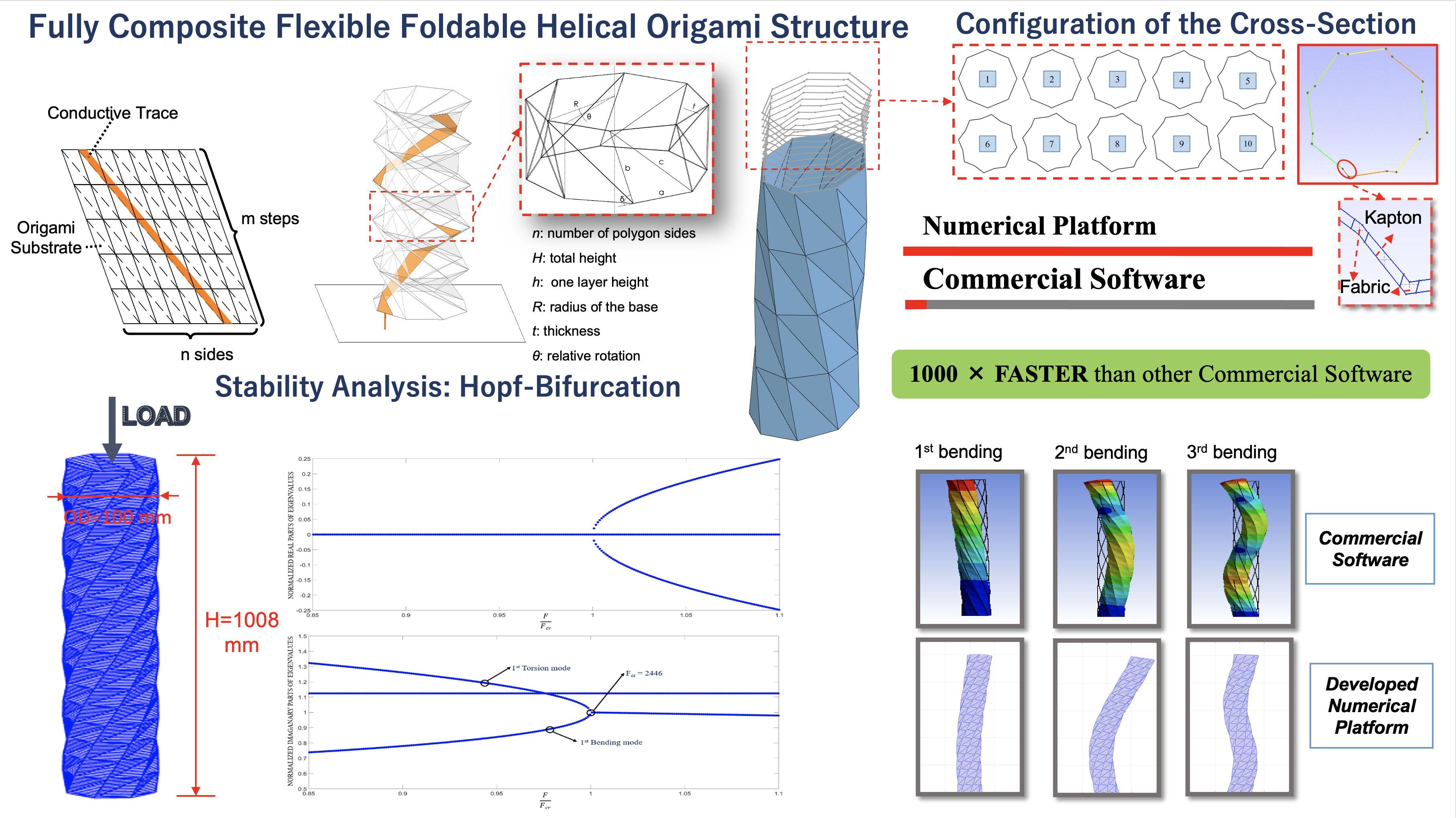
Figure 3: Stability Analysis of a Flexible Foldable Origami Structure
- Related article: Mojtaba Moshtaghzadeh, Ehsan Izadpanahi, Pezhman Mardanpour: Stability analysis of an origami helical antenna using geometrically exact fully intrinsic nonlinear composite beam theory, Engineering Structures, Volume 234, 2021. http://10.1016/j.engstruct.2021.111894
DESIGN WITH CONSTRUCTAL THEORY IN AEROELASTIC SYSTEMS
The intellectual emphasis on design proceeds from the constructal law, which provides insight into “evolutionary design” and how to improve technology for human benefit. This body of research explores the interplay between the constructal law, and aeroelasticity (aerodynamics, dynamics, elasticity). This research has two fundamental applications. One application involves using the constructal law to discover, explain, and predict the occurrence of flow configurations, whether natural or engineered. The other application uses the constructal law to advance a philosophy of design as science – not opinion – which can help us develop faster, cheaper and more reliable strategies for generating the geometry that is missing from our designs.
INFLECTED WINGS IN FLIGHT: UNIFORM FLOW OF STRESSES MAKES STRONG AND LIGHT WINGS FOR STABLE FLIGHT
Flying animals morph and flex their wings during their flight. Their wings morph with the turbulent flow created around them. The wings of modern airplanes do not have this ability. In this study we show that the ability to flex the wings leads to greater stability (higher flutter speed), and that this is due to the more uniform distribution of stresses in the flexing wing. This way the flexing wing becomes the lightest per unit of flapping force, or the strongest per unit of weight; Fig. 4.
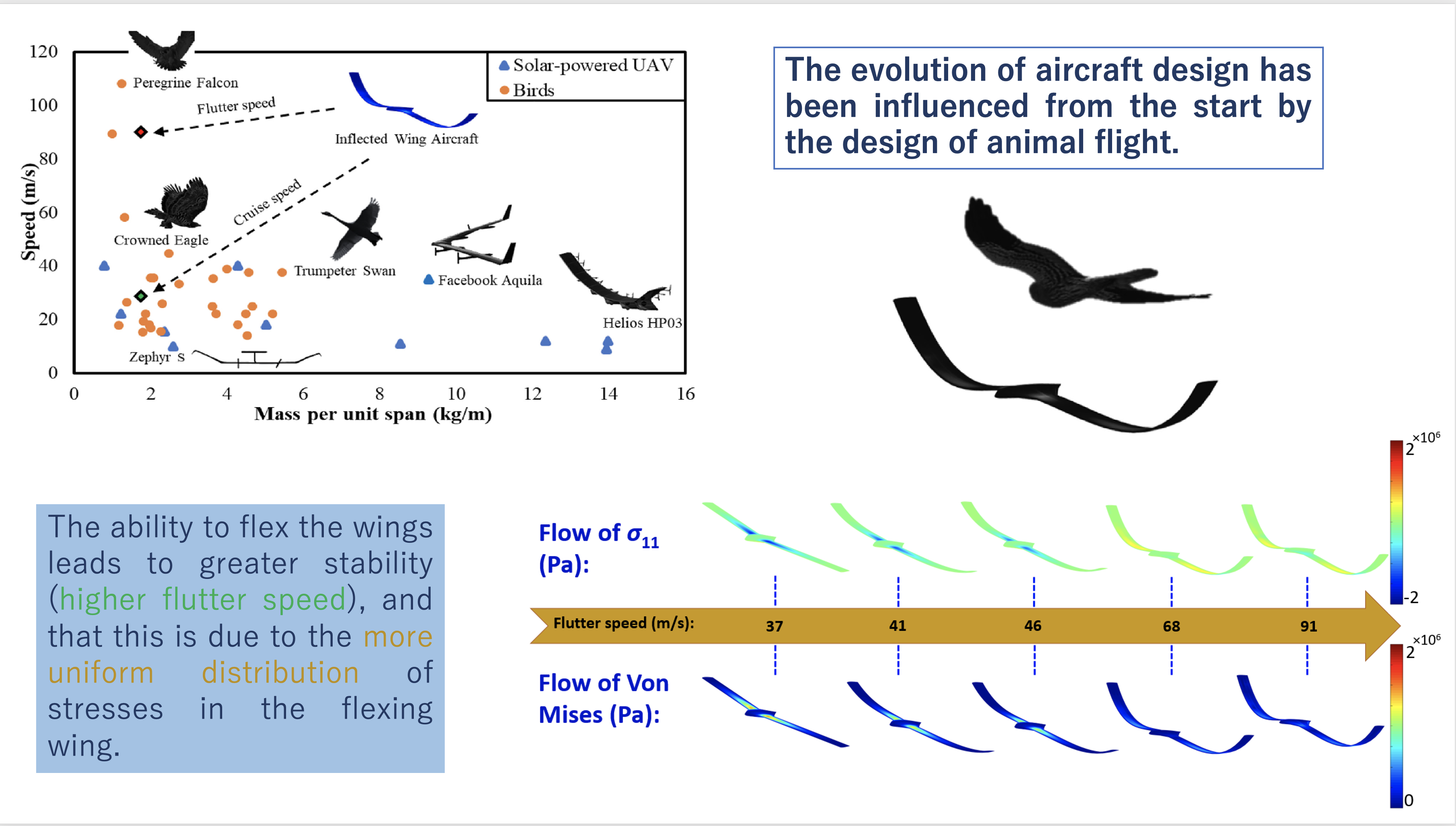
Figure 4 – Inflected wing and aeroelastic stability
- Related article: Mardanpour, Pezhman, Ehsan Izadpanahi, Shanae Powell, Siavash Rastkar, and Adrian Bejan. “Inflected wings in flight: uniform flow of stresses makes strong and light wings for stable flight.” Journal of Theoretical Biology 508 (2021): 110452. https://doi.org/10.1016/j.jtbi.2020.110452
CONSTRUCTAL DESIGN OF FLYING WING AIRCRAFT: CURVED AND SWEPT CONFIGURATIONS
Constructal law considers the design as a physics principle and uses energy flow configurations (e.g., the flow of stresses through the structure) to explain and predict the time arrow of change and evolutionary design in nature. Here, constructal law is used to explain why swept flying wings achieve higher flutter speed compared with curved wings. This investigation of the aeroelastic instability through the lens of constructal law is a new concept that envisions the evolutionary design of aircraft. Nonlinear Aeroelastic Trim And Stability of HALE Aircraft (NATASHA) performs the aeroelastic stability analyses. NATASHA benefits from geometrically exact, fully intrinsic, composite beam formulation of Hodges combined with Peters aerodynamic model. Variational Asymptotic Beam Sectional Analysis (VABS) conducts stress analysis. The results shed light on how changing the geometry would affect the flow of stresses and stability. The findings reveal an analogy between the instability and stress flow strangulation in the structure. Stress strangulation is observed in both configurations, whereas the curved configuration has lower flutter speed and stress strangulation with larger magnitude. The swept wing configuration provides easier access to the flow of stresses with less stress strangulation and leads to a more stable configuration; Fig. 5.
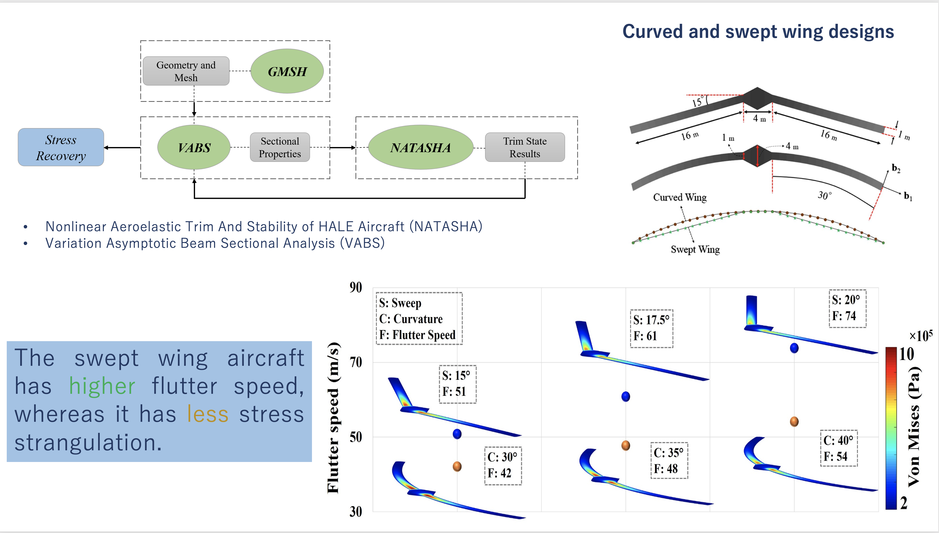
Figure 5 – Evolutionary design: Aeroelastic stability of curved vs. swept wing and flow of stresses
- Related article: Izadpanahi, Ehsan, Siavash Rastkar, and Pezhman Mardanpour. “Constructal Design of Flying Wing Aircraft: Curved and Swept Configurations.” AIAA Journal 57, no. 12 (2019): 5527-5542. https://doi.org/10.2514/1.J058315
EVOLUTIONARY AEROELASTIC DESIGN OF FLYING-WING CROSS SECTION
The uniform distribution of stresses in flying-wing aircraft improves the aeroelastic flight envelope. In this paper, we document the effect of wing cross-section configuration on the stress distribution and flutter characteristics of a flying-wing aircraft. We determined the flow of stresses through the wing structure, and changed the structure to avoid stress strangulations. The emerging structure is more stable. We used the computer programs Gmsh, Variational Asymptotic Beam Sectional Analysis, and Nonlinear Aeroelastic Trim and Stability of High Altitude Long Endurance Aircraft. The wing structure was evolved by holding fixed the flight condition, mass per unit length, and material type. The results indicate that particular configurations of wing cross sections favor a uniform stress distribution, and therefore aeroelastic stability. The configuration with higher flutter speed is associated with the smoother flow of stresses through the wing structure; Fig. 6.
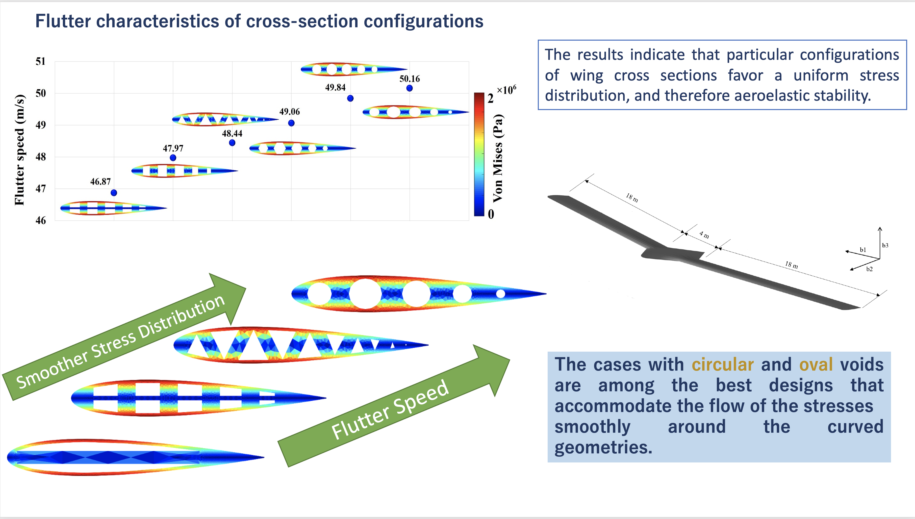
Figure 6 – Flow of stresses in wing cross-section and aeroelastic stability of flying wing aircraft
- Related article: Moshtaghzadeh, Mojtaba, Ehsan Izadpanahi, Adrian Bejan, and Pezhman Mardanpour. “Evolutionary Aeroelastic Design of Flying-Wing Cross Section.” AIAA Journal (2021): 1-12. https://doi.org/10.2514/1.J060410
CONSTRUCTAL DESIGN OF AIRCRAFT: FLOW OF STRESSES AND AEROELASTIC STABILITY
“Body-freedom flutter characteristics of flying wing aircraft vary with engine placement. Here, we show why a certain design parameter (engine placement) influences the aeroelastic flight envelope of the aircraft. The approach is based on the constructal law and the principle that a design that avoids stress strangulations provides better access to the flows that inhabit the system. This is in sharp contrast with trial-and-error techniques such as optimization, which means to opt from among different choices, cases, and designs. Under the same flight condition, the flow of stresses through the aircraft wings is investigated for several configurations including those with maximum and minimum flutter speeds. The results reveal that when the stresses flow smoothly in the wings the stability of the aircraft improves. On the other hand, in the cases in which the engine location causes stress strangulation, the flutter speed decreases considerably. The most severe stress strangulation corresponds to the aircraft configuration with minimum flutter speed (i.e., engine placement at 20% span behind the reference line). The smoothest flow of stresses happens in the configuration with maximum flutter speed (i.e., engine placement at 80% span forward of the reference line)” ; Fig. 7.
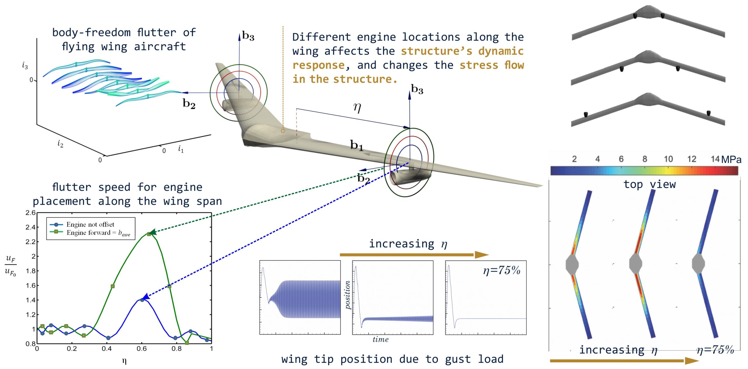
Figure 7: Constructal Design of Aircraft: Flow of stresses and Aeroelastic Stability
- Related article: Mardanpour, Pezhman, Ehsan Izadpanahi, Siavash Rastkar, Sylvie Lorente, and Adrian Bejan. “Constructal design of aircraft: flow of stresses and aeroelastic stability.” AIAA Journal 57, no. 10 (2019): 4393-4405. https://doi.org/10.2514/1.J057183
PASSIVE MORPHING OF FLYING WING AIRCRAFT
In a novel approach, the analysis underlying NATASHA was extended to include the ability to simulate morphing of the aircraft. An example of the kind of morphing we looked at requires the wings to fold such that solar panels installed on the wings receive solar rays more directly at specific times of the day; see Fig. 8. Because of the “long endurance” feature of HALE aircraft, such morphing needs to be done with as near zero-energy cost as possible.
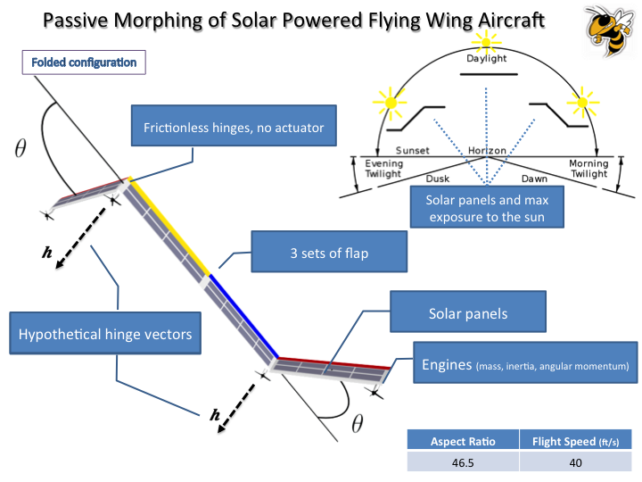
Figure 8: Passive Morphing of Solar Powered Flying Wing Aircraft.
Our aeroelastic simulations have shown that near zero-energy morphing is feasible. Indeed, we demonstrated that it is possible to morph a folding wing configuration using only the flight control flaps and the aero-dynamic forces. A locking pin is removed, and the control surface is deflected, thus changing the aerodynamic forces and causing the wing to fold. When the fold angle is at the desired value, the control surface again changes its deflection, causing the folding mechanism to come to a stop, at which point the locking pin is reinserted. This maneuver is called passive morphing.
Related Articles:
- Mardanpour, Pezhman; and Hodges, Dewey H.: Passive Morphing of Flying Wing Aircraft: Z-shaped Configuration, Journal of Fluids and Structures, vol. 50, pp. 1716 –1725, 2013.
- Mardanpour, Pezhman; and Hodges, Dewey H.: On the Importance of Nonlinear Aeroelasticity and Energy Efficiency in Design of Flying Wing Aircraft, Journal of Advances in Aerospace Engineering. vol. 2015, Article ID 613962, 11 pages, 2015.
FLUTTER SUPPRESSIN OF FLYING WING AIRCRAFT
One common configuration of High-Altitude Long-Endurance (HALE) aircraft is the “flying wing.” They may exhibit a dynamical instability called body-freedom flutter, which occurs when the short-period mode of the aircraft couples with the elastic mode of the wings. The long endurance feature dictates that the aircraft be made of lightweight material that typically leads to more flexibility and larger deformations. The challenge of modeling such phenomena particularly arises when one needs to extend the flight envelope without increasing the stiffness and weight of the structure.
Nonlinear Aeroelastic Trim And Stability of Hale Aircraft, NATASHA, is the computer program used to simulate the aeroelastic behavior of these aircraft. NATASHA uses Nonlinear Composite Beam Theory of Hodges and the finite state induced airflow model of Peters et al. The engines were modeled as follower forces with mass, inertia, and angular momentum, and the flying wing, whose geometry was similar to Horten IV, was modeled as a beam-like structure with initial twist and curvature. Extensive parametric studies were carried out on two-engine and four-engine configurations, and NATASHA’s results showed that the aeroelastic flight envelope could be extended up to four times of the base model by right choice of engine placement; see figure 9. A thorough flutter calculation for all possible engine placements is computationally expensive. My research provides a methodology for finding the highest flutter zone with the potential to increase the flutter speed while using the area of minimum kinetic energy of the unstable mode.

Figure 9: Effect of Engine Placement on Aeroelastic Flight Envelope.
Related Articles:
- Mardanpour, Pezhman; and Hodges, Dewey H.: Effect of Engine Placement on Aeroelastic Trim and Stability of Flying Wing Aircraft, Journal of Aircraft, vol. 31, pp. 33 – 38, 2013.
- Mardanpour, Pezhman; Richards, Phillip W.; Nabipour, Omid; and Hodges, Dewey H.: Effect of Multiple Engine Placement on Aeroelastic Trim and Stability of Flying Wing Aircraft, Journal of Fluids and Structures, vol. 44, pp. 67 – 86, 2014.
Another aspect of my research concerns the transient excitation of an aircraft’s engines that can only be studied using time domain analysis. These excitations are large and cannot be simulated with small perturbations about an equilibrium state (i.e., the Hopf bifurcation approach in assessment of stability). In my research, the dynamic behavior of a lightweight, small-class thrust, turboshaft engine (JetCat SP5) is simulated by the JetCat SP5 engine simulator for both rectangular pulse and ramp fuel inputs. The nonlinear aeroelastic response of the wing to these kinds of excitations is examined for different engine placements along the span with offsets from the elastic axis. It was shown that these excitations are prone to limit cycle oscillation (LCO) even below flutter speed; see Fig. 10.
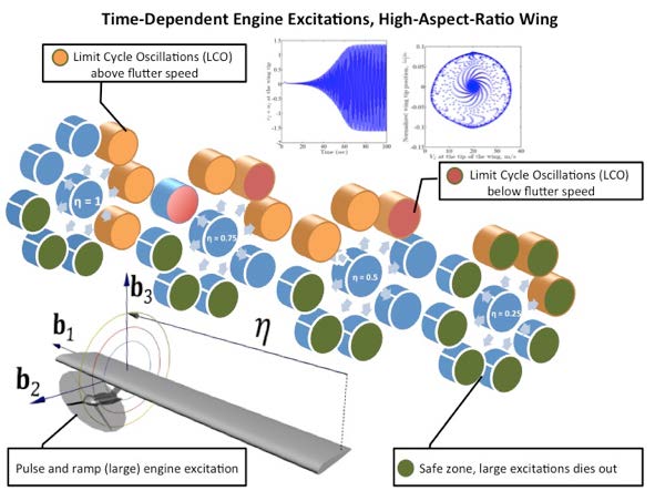
Figure 10: Effect of Engine Placement on Aeroelastic Behavior of High-Aspect-Ratio Wings.
Related Articles:
- Mardanpour, Pezhman; and Hodges, Dewey H.: Nonlinear Aeroelastic Behavior of High Aspect Ratio Wing Excited by Time-Dependent Thrust, Journal of Nonlinear Dynamics, Vol.75, pp. 475 – 500, 2014.